8
RF Device Data
Freescale Semiconductor
MRFE6VP8600HR6 MRFE6VP8600HR5 MRFE6VP8600HSR6 MRFE6VP8600HSR5
TYPICAL CHARACTERISTICS
250
109
90
TJ, JUNCTION TEMPERATURE (°C)
Figure 12. MTTF versus Junction Temperature -- CW
Note:
The MTTF calculation for this graph is based on the thermal
resistance of the part using thermal grease TIM mounting.
MTTF calculator available at http://www.freescale.com/rf. Select
Software & Tools/Development Tools/Calculators to access MTTF
calculators by product.
107
106
104
110 130 150 170 190
MTTF (HOURS)
210 230
108
105
VDD
=50Vdc
Pout
= 125 W CW
VDD
=50Vdc,IDQ
= 1400 mA, Pout
= 125 W Avg.
f
MHz
Zsource
?
Zload
?
860
1.14 + j0.88
2.61 + j1.84
Zsource
= Test circuit impedance as measured from
gate to gate, balanced configuration.
Zload
= Test circuit impedance as measured
from drain to drain, balanced configuration.
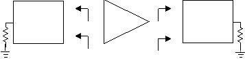
Figure 13. Series Equivalent Source and Load Impedance
Zsource
Zload
Input
Matching
Network
Device
Under
Test
Output
Matching
Network
--
-- +
+


发布紧急采购,3分钟左右您将得到回复。
相关PDF资料
MRFG35002N6AT1
TRANS RF 1.5W 6V PWR FET PLD-1.5
MRFG35002N6T1
TRANSISTOR RF FET 3.5GHZ PLD-1.5
MRFG35003ANR5
TRANSISTOR RF 3W 12V PLD-1.5
MRFG35003ANT1
TRANSISTOR RF 3W 12V PLD-1.5
MRFG35003M6T1
MOSFET RF 3.5GHZ 3W 6V 1.5-PLD
MRFG35003MT1
MOSFET RF 3.5GHZ 3W 12V 1.5-PLD
MRFG35003N6AT1
TRANSISTOR RF 3W 6V PLD-1.5
MRFG35003N6T1
MOSFET RF 3.5GHZ 3W 6V 1.5-PLD
相关代理商/技术参数
MRFE6VS25GNR1
功能描述:射频MOSFET电源晶体管 VHV6E 25W50V TO270-2G
RoHS:否 制造商:Freescale Semiconductor 配置:Single 晶体管极性: 频率:1800 MHz to 2000 MHz 增益:27 dB 输出功率:100 W 汲极/源极击穿电压: 漏极连续电流: 闸/源击穿电压: 最大工作温度: 封装 / 箱体:NI-780-4 封装:Tray
MRFE6VS25LR5
功能描述:射频MOSFET电源晶体管 VHV6E 25W50V NI360L RoHS:否 制造商:Freescale Semiconductor 配置:Single 晶体管极性: 频率:1800 MHz to 2000 MHz 增益:27 dB 输出功率:100 W 汲极/源极击穿电压: 漏极连续电流: 闸/源击穿电压: 最大工作温度: 封装 / 箱体:NI-780-4 封装:Tray
MRFE6VS25N
制造商:FREESCALE 制造商全称:Freescale Semiconductor, Inc 功能描述:RF Power LDMOS Transistor
MRFE6VS25NR1
功能描述:射频MOSFET电源晶体管 VHV6E 25W50V TO270-2 RoHS:否 制造商:Freescale Semiconductor 配置:Single 晶体管极性: 频率:1800 MHz to 2000 MHz 增益:27 dB 输出功率:100 W 汲极/源极击穿电压: 漏极连续电流: 闸/源击穿电压: 最大工作温度: 封装 / 箱体:NI-780-4 封装:Tray
MRFE6VS25NR1-CUT TAPE
制造商:Freescale 功能描述:MRFE6VS Series 2000 MHz 25 W 50 V N-Channel RF Power Mosfet - TO-270-2
MRFG35002N6AT1
功能描述:射频GaAs晶体管 1.5W 6V GAAS FET PLD1.5 RoHS:否 制造商:TriQuint Semiconductor 技术类型:pHEMT 频率:500 MHz to 3 GHz 增益:10 dB 噪声系数: 正向跨导 gFS(最大值/最小值):4 S 漏源电压 VDS: 闸/源击穿电压:- 8 V 漏极连续电流:3 A 最大工作温度:+ 150 C 功率耗散:10 W 安装风格: 封装 / 箱体:
MRFG35002N6R5
功能描述:TRANSISTOR RF 1.5W 6V POWER FET RoHS:是 类别:分离式半导体产品 >> RF FET 系列:- 产品目录绘图:MOSFET SOT-23-3 Pkg 标准包装:3,000 系列:- 晶体管类型:N 通道 JFET 频率:- 增益:- 电压 - 测试:- 额定电流:30mA 噪音数据:- 电流 - 测试:- 功率 - 输出:- 电压 - 额定:25V 封装/外壳:TO-236-3,SC-59,SOT-23-3 供应商设备封装:SOT-23-3(TO-236) 包装:带卷 (TR) 产品目录页面:1558 (CN2011-ZH PDF) 其它名称:MMBFJ309LT1GOSMMBFJ309LT1GOS-NDMMBFJ309LT1GOSTR
MRFG35002N6T1
功能描述:TRANSISTOR RF FET 3.5GHZ PLD-1.5 RoHS:否 类别:分离式半导体产品 >> RF FET 系列:- 产品目录绘图:MOSFET SOT-23-3 Pkg 标准包装:3,000 系列:- 晶体管类型:N 通道 JFET 频率:- 增益:- 电压 - 测试:- 额定电流:30mA 噪音数据:- 电流 - 测试:- 功率 - 输出:- 电压 - 额定:25V 封装/外壳:TO-236-3,SC-59,SOT-23-3 供应商设备封装:SOT-23-3(TO-236) 包装:带卷 (TR) 产品目录页面:1558 (CN2011-ZH PDF) 其它名称:MMBFJ309LT1GOSMMBFJ309LT1GOS-NDMMBFJ309LT1GOSTR
